Assembly of Structural Joints Using High Tensile Steel Bolts was published in January 1951. Fillet welding refers to the process of joining two pieces of metal together whether they be.
Structural Steel Drawings
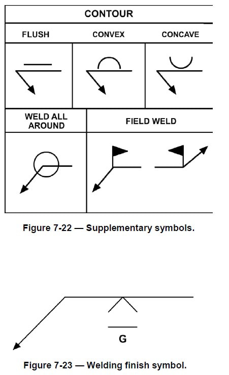
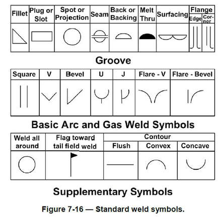
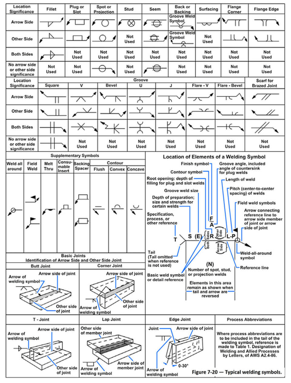
Welding Symbols Welding symbols are used on blueprints and drawings to show where the weld is to be placed and may also show the size type of weld number of welds details about the weld and even details about the joint.
. The symbol is interpreted as a simplified cross-section of the weld. Top Project-specific requirements Because BS EN 1090-2 4 is a comprehensive document for all steel products and types of structure it includes numerous instances where options need to be selected or alternatives specified. Using it you can import networks to AutoCAD create longitudinal profiles check crossing points and export.
Lets start with architectural symbols which are typically larger and will be drawn into floor plans first. Free Electrical Symbols block and drawings for design block diagram wiring system architecture and more autocad drawing in dwg file formats for use with autocad and other 2D and 3D design software. Structural steel blueprint symbols.
The structural plans usually are numbered beginning with S as in S 001 These plans include reinforcement foundations slab thicknesses and framing materials lumber concrete pilasters structural steel concrete block etc. A tool for smart and simple geometric modeling of pipe networks. Styles and Standards 1.
Surface model analysis 1. 18 scale fully dimensioned note and schedule all footing and column sizes. More recently engineers and draftsmen use the drawing board for making and modifying drawings on paper with ink or pencil.
Each was developed through the deliberations and approval of the full Council membership and based upon past successful usage advances in the state of knowledge and changes in engineering design. Bolts and bolted joints 34 5. Plumbing Piping and Valves Symbols.
Read the structural plans. Steel bridgesÑcase studies 170 Appendix. Recommended Drawing Numbering Scales and Dimensioning 1 3.
Suggestion for Exchange Store 1. Include items such as lap spice details lintel details footing step details beam to beam and beam to column connections etc S100 Foundation Plan. Structural Design 1.
Surface Laptop 4 1. Autodesk AutoCAD add-on to build and manage block libraries that enhance your ability to catalog and manipulate DWG symbols and drawings. Robot Structural Analysis.
Doors windows stairwells walls cabinets and sinks are examples of these. This engineering drawing present weld type symbols and fillet weld symbols. Since that time the Council has published seventeen successive editions.
The weld type symbol is typically placed above or below the center of the reference line depending on which side of the joint its on. Our family of fire rated products retain their structural ability and strength while protecting you from flames smoke and gas. Standard Handrail Systems Tri Tech Inc.
They became more utilitarian and were built of steel and plastic instead of fine woods and brass. Beam splices typically resist large Bending Moments and shear forces and it is typically assumed that the flange splice carries the moment forces while the web splice carries the shear Ideally the splice should be located away from the point of maximum deflection. Rules for Drawing Symbols.
S000 Typical details and notes. In case it is required to show exact location the dimensions. Design detailing of major steel components 67 7.
List of comparative symbols xiv 1. Section properties 213 Bibliography 235 British Standards and other standards 237 ASTM. Draughting practice for detailers 18 4.
Tri Techs standard rail system allows for pipe picket shoe mount cable and glass grip features to be built in. Different drawing instruments set square protractor etc are used on it to draw parallel perpendicular or oblique lines. Let us discuss the above blueprints one by one.
UK DoPs for hot rolled structural steel sections from British Steel are available here and a UK DoP for fabricated steelwork can be found here. Where this is not possible particularly in the case of heavy plate girders it must be designed so that the web splice. Reading blueprints generally requires a strong.
Alway be sure about scale of symbols and drawing they must be same. Steel buildingsÑcase studies 115 8. There are instruments for.
Always use a standard size of symbol otherwise it misjudge the space around it. Keep location of symbol on drawing approximatley correct. Here are the different aspects of the structural plans that you will need to read.
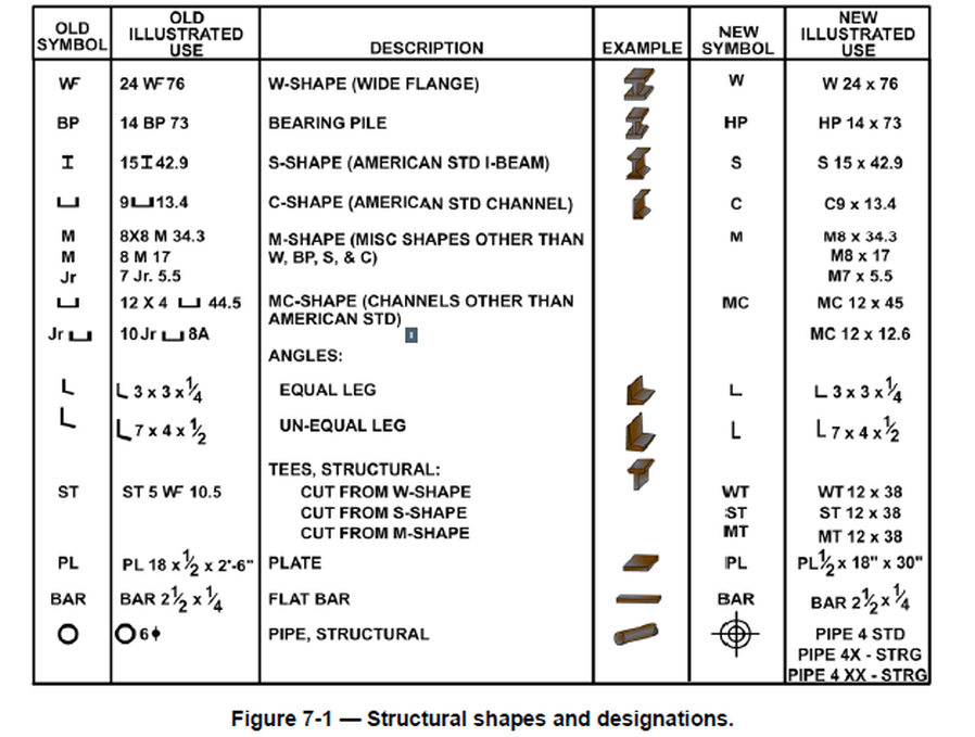
Structural steel 4 3. Welding symbols are the integral part and the basic requirements for fabrication as they provide vital information for the joint location weld size length weld type as well as quality requirements on the fabrication or construction drawing. The scheme for the symbolic representation of welds on engineering drawings used with the third angle method of.
Use readymade templates to increase the speed and clarity of the symbols. Schedules can appear on. Omega-Lite Aluminum Composite Panels Laminators Incorporated.

Structural Plan Symbols Archtoolbox
Structural Steel Drawings

How To Read Structural Steel Drawings Directorsteelstructure
Structural Steel Drawings
Chapter 7 Structural And Architectural Drawings
Structural Steel Drawings

Pin On Master
Structural Steel Drawings
0 comments
Post a Comment